


Reactive power compensation
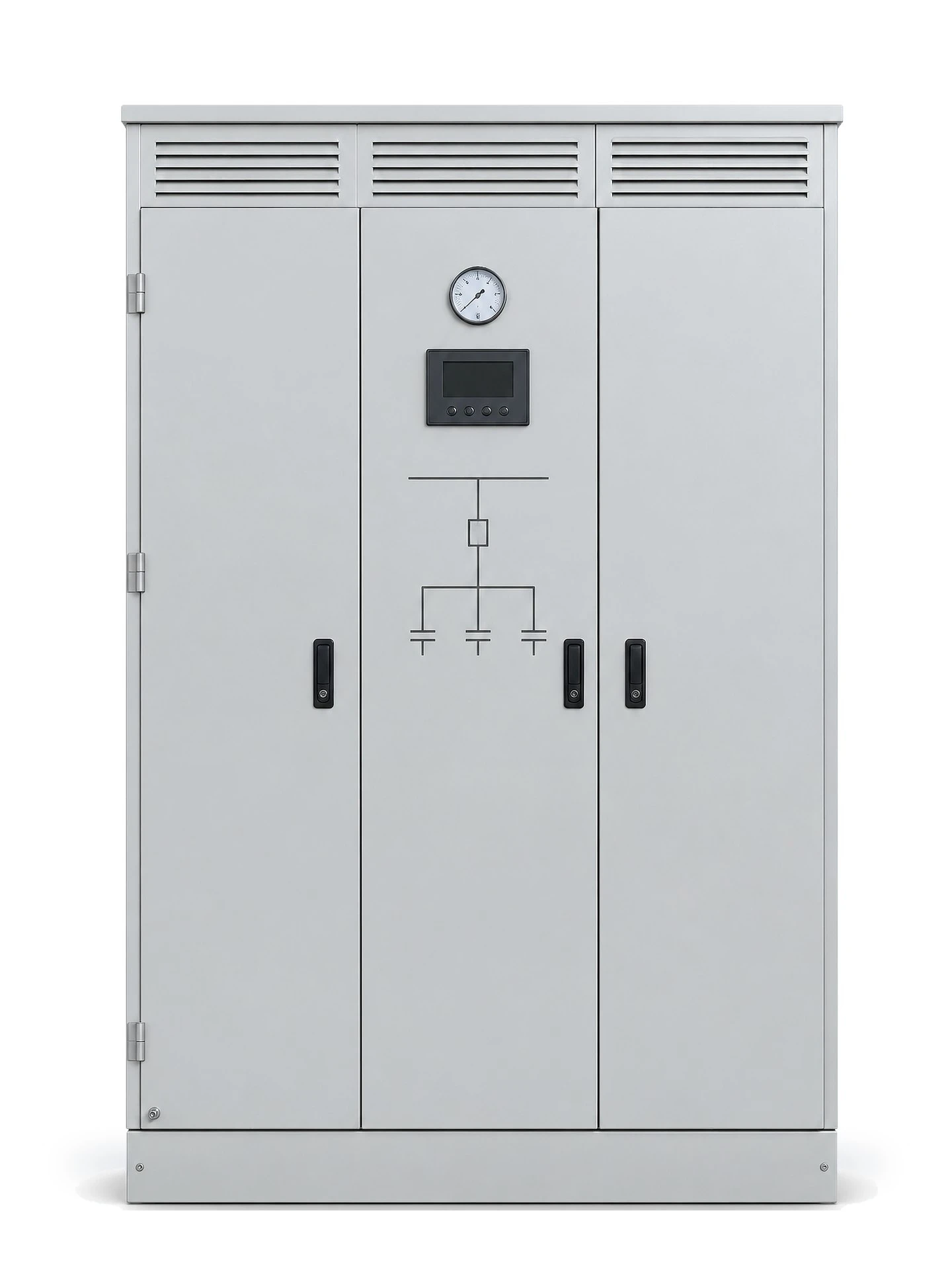
Shunt capacitor bank enclosures for fixed and automatic compensation, built for system voltages from 3 kV to 220 kV.
- 3-220 kV System voltage
- 33 Voltage classes
- 0 / 6 / 12 % Reactor rate
Voltage coverage
Thirty-three system voltages from one platform
Each class is engineered with its own insulation level, creepage distance and bank arrangement. Nothing is scaled up from a lower class.
Medium voltage, 3 kV to 24 kV
21 classes
3 kV, 3.3 kV, 3.6 kV, 4.15 kV, 6 kV, 6.3 kV, 6.6 kV, 6.9 kV, 7.2 kV, 10 kV, 10.5 kV, 11 kV, 12 kV, 13.8 kV, 15 kV, 17.5 kV, 20 kV, 21 kV, 22 kV, 23 kV, 24 kV.
High voltage, 27.5 kV to 72.5 kV
8 classes
27.5 kV, 30 kV, 33 kV, 34.5 kV, 35 kV, 36 kV, 66 kV, 72.5 kV.
Extra high voltage, 110 kV to 220 kV
4 classes
110 kV, 130 kV, 145 kV, 220 kV.

Construction
Eight building blocks in one enclosure
A capacitor bank is only as reliable as its weakest link. Every block is selected for the voltage class it serves.
- Vacuum switching device Circuit breaker or switch-disconnector rated for the class, with a visible break before the bank is opened.
- Zinc-oxide surge arrester Clamps switching and lightning overvoltages at the bank terminals, protecting the capacitor units from dielectric stress.
- Current transformers Feed the controller and the protection relay with true bank current, for power factor regulation and unbalance detection.
- HV shunt capacitor units Rack-mounted units in single or double star, sized per project kilovar and arranged for even ventilation.
- Series reactor 6 or 12 percent detuning keeps the bank off the 5th and 3rd harmonic and limits the inrush current.
- Discharge coil Drains the residual voltage below 75 V after switching off, which is what makes maintenance access possible.
- Controller and protection Automatic power factor target, step switching, overvoltage and unbalance protection, with the event log on the front door.
- Ventilation and pressure relief Louvered intake and exhaust sized for the bank losses, with pressure relief for internal fault conditions.
Configuration
Specified for the class, not for a catalogue
| Rated system voltage | 3 kV to 220 kV, 33 classes |
|---|---|
| Rated frequency | 50 Hz or 60 Hz |
| Rated output | Made to order, kilovar per project |
| Connection | Single star or double star |
| Reactor rate | 0, 6 or 12 percent, detuned |
| Switching | Vacuum breaker or switch-disconnector |
| Control mode | Fixed or automatic power factor control |
| Bus system | Copper busbar, insulated |
| Enclosure | Sheet steel, indoor or outdoor |
| Design reference | IEC 60871-1 and GB/T 11024.1 |
| Testing | Routine factory tests before shipment |
Where it is installed
- Substations
- Steel and metallurgy
- Mining
- Cement
- Chemical and petrochemical
- Wind and solar farms
- Electrified railway
- Industrial grids
Enquiry
Built to your system voltage
Send the single line diagram and the target power factor. We return a bank arrangement, a GA drawing and a quotation for any class from 3 kV to 220 kV.

Capacity calculation
Kilovar and step size from your load profile.
GA drawing and single line diagram
Layout, clearances and busbar arrangement.
Routine factory tests
Test reports issued with every enclosure.