


Send us the motor nameplate - rated voltage, rated current, load type and starts per hour. We
confirm the starting duty and the fuse / contactor rating before quoting, so the quote matches
the motor rather than the catalogue.
10 kV, 450 kW - Soft Start Without the Inrush
Thyristor soft starter in a single metal-enclosed cabinet: programmable start profile, soft stop for pumps
and conveyors, vacuum bypass, and a protection boundary that stays clear of the upstream switchgear.

Eight Devices in Series, One Phase at a Time
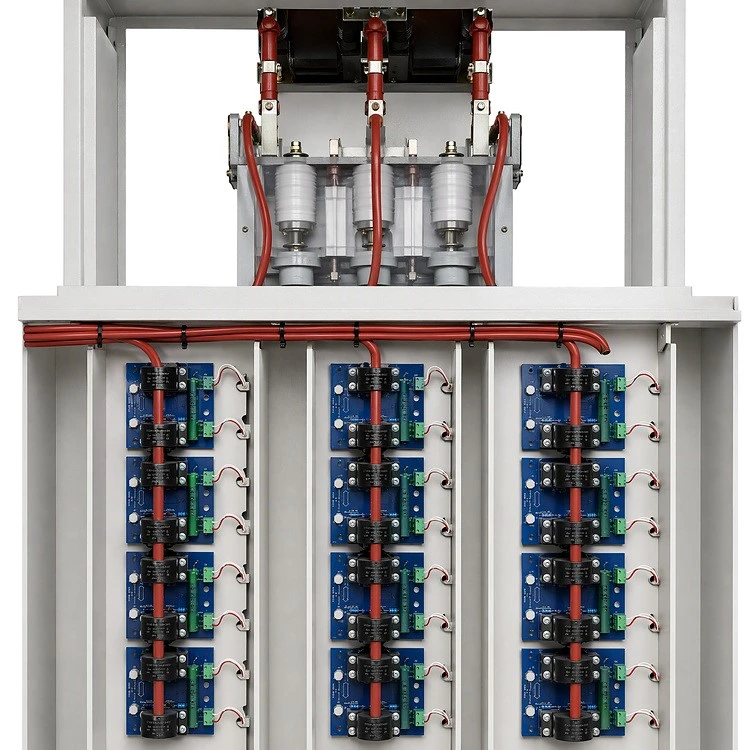
Each phase is its own string of eight thyristors, and every device carries a dedicated gate-drive and
snubber board on a separate PCB. The series connection is made with flexible bus rather than rigid
bar, so thermal cycling loads the conductors instead of the disc contacts. Insulating barriers keep the
three phase strings electrically separated inside the same compartment.
① Eight thyristors in series per phase
② Individual gate-drive / snubber board per device
③ Flexible series bus, thermal-cycling tolerant
④ Phase-to-phase insulating barriers
The Contactor Carries the Load, Not the Semiconductors
When the motor reaches rated speed the bypass vacuum contactor closes and takes over running current,
so the thyristor string works only during start and stop. That single decision is what separates a starter that
lasts fifteen years from one that fails in the third. Epoxy bushings and cast-resin CTs sit in the same
compartment, keeping the current path short.
① Vacuum contactor, bypass duty
② Epoxy through-wall bushings
③ Cast-resin current transformers

Short-Circuit Protection That Reports Itself
Three high-voltage current-limiting fuses sit in the main circuit, each with a striker that trips a micro-switch
on blow. A blown fuse therefore shows up as an alarm and a blocked start, not as a silent single-phasing
that cooks the motor. The clear front shield is a touch barrier only - the insulation is the fuse body and its
epoxy supports.
① HV current-limiting fuse, one per phase
② Striker + micro-switch, blown-fuse signal to controller
③ Clear shield: touch barrier, not insulation

Measurement and Earth Fault, Both Taken Care Of
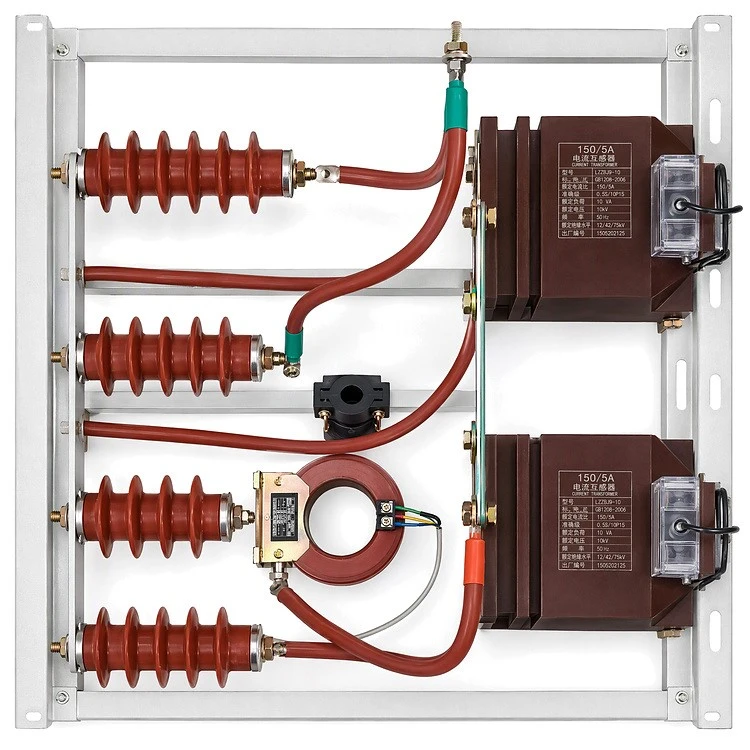
Phase current transformers on epoxy post insulators feed the controller for current-limited starting and
running indication. A core-balance CT surrounds the three phases for earth-fault detection, so a
winding-to-frame fault is caught at the starter instead of at the upstream relay.
① Phase CTs for starting control and metering
② Core-balance CT for earth-fault detection
③ Epoxy post insulators, four-point support
Phase-Identified Busbar on Cast Epoxy Supports
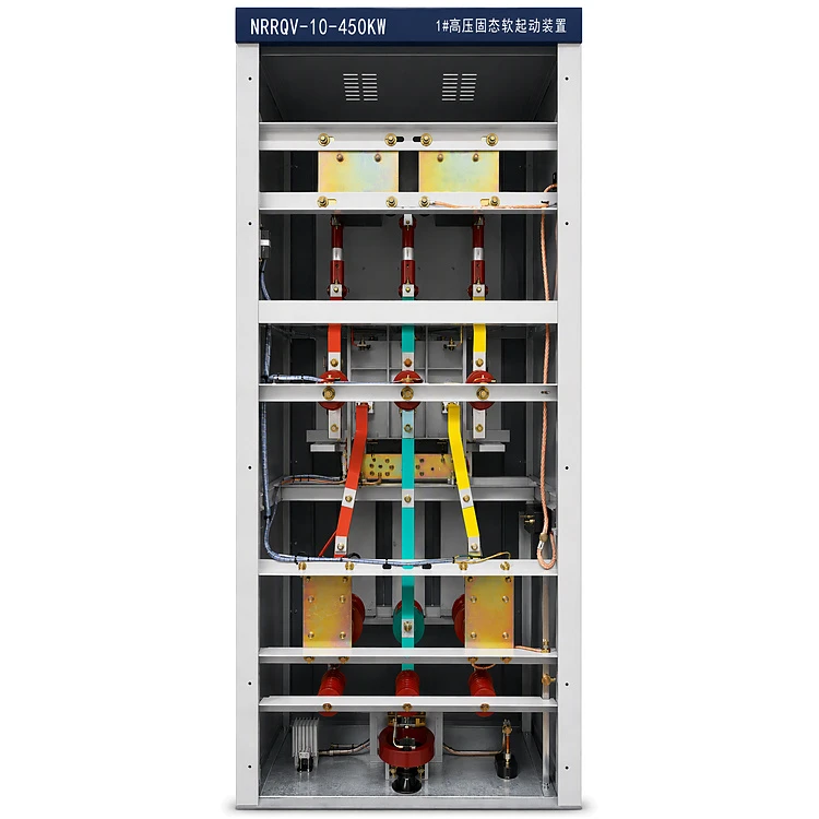
The three-phase busbar runs vertically on epoxy post insulators with insulating partitions between
compartments, keeping phase-to-phase and phase-to-earth distances constant along the whole height
of the cabinet. The earthing bar is brought out at the base for a single-point connection on site.
① Three-phase copper busbar, phase identified
② Epoxy post insulators
③ Inter-compartment insulating partitions
④ Base earthing bar
Labelled, Ducted, Segregated
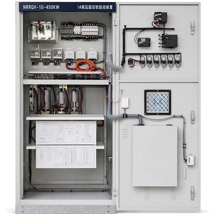
Every conductor carries a printed ferrule and every device a designation, so a fault can be traced from
the terminal list without pulling the harness apart. CT secondaries run in their own orange leads, control
wiring sits in slotted duct, and the power and control compartments are physically separated.
① Ferruled conductors and printed device designations
② CT secondary wiring separated from control wiring
③ Power / control compartment segregation
Control Logic You Can Read Without a Laptop
Fourteen interposing relays and two timers are laid out in one row with printed designations, so the start
sequence can be followed relay by relay on the door. The pushbutton station and selector switches sit on
the same panel, which keeps local operation and local diagnosis in one place.
① KA1–KA14 interposing relays with designations
② KT1 / KT2 timers
③ Pushbutton and selector station on the same door

Isolated Supplies for the Electronics at Line Potential
Three switching supplies run control power, and three isolated high-frequency rectifier modules - one per
phase group - feed the gate-drive electronics that sit at line potential. Isolation is done in the supply
instead of being improvised on the driver board, which is where most solid-state starters quietly lose their margin.
① Three control-power supplies
② Three isolated high-frequency rectifier modules
③ Segregated terminal strips and MCBs

Local Control Where the Operator Stands
A touchscreen HMI, start and stop pushbuttons, an emergency stop, two selector switches and a
key-operated lockout on one door. The starting-circuit mimic diagram is printed below, so the current
path can be checked before anything is closed.
① Touchscreen HMI
② Start / stop / emergency stop
③ Key-operated lockout
④ Starting-circuit mimic diagram

Live-Line Indication and Door Interlock
The DXN live-line indicator, six phase lamps and the interlock rod are all on the door: the operator
confirms the circuit is dead before the door opens, and the rod prevents opening while the isolating
contact is closed.
① DXN live-line indicator
② Six phase indicator lamps (HL1–HL6)
③ Door interlock rod

Drawings That Stay With the Unit


Hot Tags: 10kv 450kw solid state soft starter, China 10kv 450kw solid state soft starter manufacturers, suppliers, factory, advanced motor soft start, motor soft start for communicating with other components, motor soft start for compressors, motor soft start for coordinating with other operations, motor soft start for intelligent control of motors, motor soft start for wireless control of motors